Most factory network vulnerabilities aren’t the result of sophisticated attacks. They’re the result of infrastructure that was never properly designed in the first place.
Manufacturing was the most-targeted industry for cyberattacks for the third consecutive year — accounting for more than one in four incidents IBM X-Force responded to globally. The entry point in most of those incidents wasn’t a zero-day exploit. It was a flat, unsegmented plant network where a compromised endpoint could reach PLCs, SCADA systems, and ERP platforms without passing through a single meaningful security boundary.
When a production line goes down because of a network architecture failure, the financial damage starts accumulating within minutes. Lost throughput, missed shipments, emergency response costs, and the reputational fallout with customers who depend on your delivery commitments are all downstream consequences of design decisions — or the absence of any deliberate design at all.
This guide explains how factory networks are structured, where legacy approaches create operational and security risk, and what the right architecture actually looks like for a modern manufacturing environment.
Factory network architecture is the structured framework that connects sensors, machines, controllers, and business systems across a manufacturing environment. It governs how data moves from a temperature sensor on a production line to an ERP system in the front office — and it determines whether that data arrives in time to matter.
This is not a background IT concern. Industrial communication in plant-floor systems is often millisecond dependent, and some motion-control traffic operates at microsecond precision. A dropped packet in an enterprise environment triggers a retry. The same event on a production line can halt a conveyor, crash a robotic arm sequence, or trigger an emergency stop.
Factory network architecture spans three distinct layers:
A breakdown or misconfiguration at any one of these layers propagates consequences across the others — whether that means a line stoppage, a compliance failure, or an open path for an intrusion.
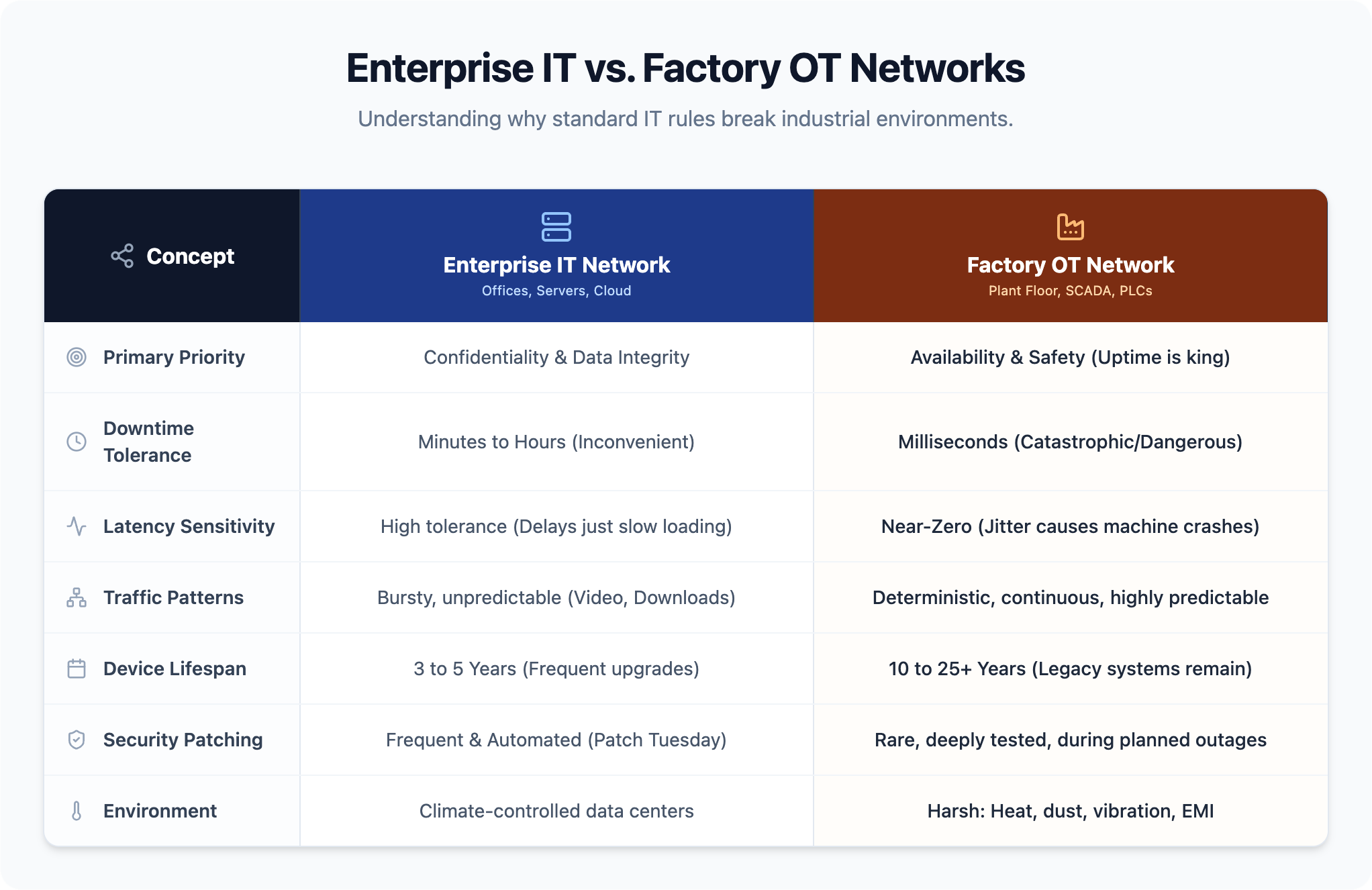
Most IT professionals trained on enterprise networks encounter a steep learning curve the first time they step onto a plant floor, because the design priorities are fundamentally reversed.
| actor | Enterprise IT Network | Factory OT Network |
|---|---|---|
| Primary priority | Data throughput | Deterministic timing |
| Downtime tolerance | Scheduled maintenance windows | Near-zero tolerance |
| Device lifespan | Refresh every few years | 15–20 years of operation |
| Environment | Climate-controlled offices | Harsh industrial conditions |
| Traffic patterns | Bursty, variable | Cyclic, predictable |
| Security model | Regular patches and updates | Air-gapped legacy design |
The device lifespan gap carries especially serious operational consequences. Industrial network equipment routinely runs 15 to 20 years, which means the PLCs, switches, and controllers on your floor today may predate modern cybersecurity standards entirely. Any architecture strategy must account for hardware that will still be running a decade from now — including equipment that cannot be patched without full operational revalidation.
Understanding factory network design means following the path data travels from a physical machine to a business decision. Modern manufacturing networks are built in discrete layers, each with a defined function — and the architecture governing how those layers communicate directly determines how fast operations teams can respond to problems and how exposed the entire facility is to disruption.
Device Level At the base sit physical assets: sensors measuring temperature and pressure, actuators opening valves, drives controlling motor speed. These devices communicate upward through sensor buses and fieldbuses to controllers. Network latency at this layer is a production quality concern, not an IT metric.
Control Level PLCs and distributed control systems execute automation logic, process real-time device data, and send commands back down in tight control loops. This layer operates continuously and cannot tolerate interruptions without stopping production.
Supervisory Level SCADA systems and HMIs give operators visibility across multiple controllers simultaneously. This layer aggregates data for monitoring, alarming, and manual intervention — where operators see the plant as a whole rather than individual machines.
Enterprise Level MES and ERP platforms consume production data from the supervisory layer to drive scheduling, inventory management, and quality reporting. This is where operational performance becomes a business number.
Cloud Level Edge gateways preprocess and transmit selected data to cloud platforms for analytics, machine learning, and remote monitoring across multiple sites. Only 45% of organizations report full visibility into their OT environment — and the cloud layer is often the first place that gap becomes visible.
How each layer connects to the others — and where those connections are secured or left open — is where network architecture decisions carry the most operational risk.
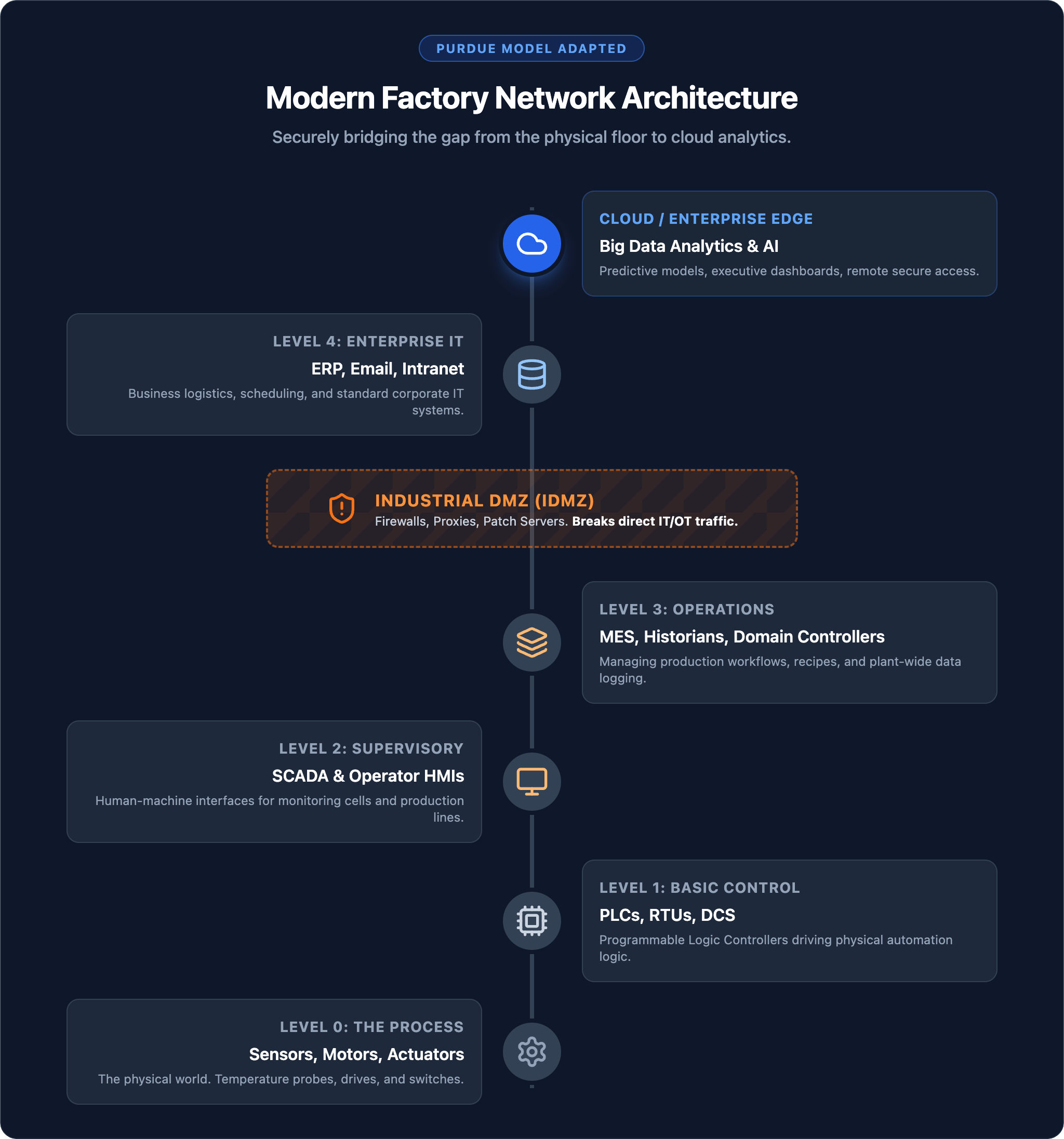
Most industrial network breaches don’t start on the plant floor. They enter through enterprise systems and move laterally because nothing meaningful stands in the way. The Purdue Enterprise Reference Architecture exists specifically to prevent that.
More than 70% of OT organizations report at least one intrusion in the past 12 months. Flat networks that treat a corporate laptop and a PLC as peers represent an unacceptable operational risk.
The Purdue model organizes industrial infrastructure into five functional levels:
| Level | Zone | What Lives Here |
|---|---|---|
| 0–1 | Physical process and basic control | Sensors, actuators, drives, PLCs |
| 2 | Area supervisory control | HMIs, engineering workstations |
| 3 | Site operations | Historians, MES servers, batch management |
| 3.5 | Industrial DMZ | Data brokers, protocol converters, secure file transfer |
| 4–5 | Enterprise IT and external networks | ERP, corporate infrastructure, internet connectivity |
The industrial DMZ at Level 3.5 is the most consequential security boundary in the entire architecture. No direct traffic should flow between enterprise networks and the plant floor. The DMZ hosts the controlled handoff point where data moves upward through edge gateways and historians without exposing control systems to enterprise traffic.
Step 1 — Map the plant floor and all data flows Complete inventory of every device: PLCs, HMIs, sensors, drives, cameras, and legacy equipment. Document traffic patterns and dependencies, particularly where a single communication failure stops an entire line. CISA advisories repeatedly identified missing asset inventories as a direct enabler of network intrusions and unplanned outages. Without this baseline, every design decision that follows is a guess.
Step 2 — Apply hierarchical architecture and segmentation Implement a structured zoning model based on the Purdue framework. An industrial DMZ at the IT/OT boundary prevents any direct traffic flow between plant-floor and business systems. Segmentation limits the blast radius of both failures and security incidents — a problem in one zone doesn’t cascade into production loss across the facility.
Step 3 — Plan IP addressing for future growth Reserve address space well beyond current device counts. Apply consistent naming conventions across all zones. Industrial network equipment commonly runs 15 to 20 years, so addressing schemes need to accommodate equipment added a decade from now, not just next quarter’s expansion.
Step 4 — Build redundancy into critical paths For any area where downtime carries severe operational cost, install redundant links, switches, and power supplies. Design networks to sustain no more than 40–50% peak utilization to absorb traffic spikes without degrading time-sensitive communications.
Step 5 — Document standards and enforce change management Maintain current network diagrams, configuration baselines, and firmware records as operational assets. Every change — a new device, a VLAN modification, a firmware update — should go through a formal approval process before implementation. In regulated environments, this directly supports FDA 21 CFR Part 11 and similar compliance requirements.
Factory network design sits at the intersection of IT and OT disciplines — and most internal teams are strong in one but not both. The result is predictable: enterprise-grade security practices never reach the plant floor, or OT systems get connected to corporate infrastructure without the segmentation and protocol controls that keep production protected.
Book a Factory Network Assessment with IT GOAT →
IT GOAT works with manufacturing operations to map network architecture decisions to specific operational goals.
The Purdue Enterprise Reference Architecture is a hierarchical framework that divides industrial networks into discrete levels with defined communication rules between them. It matters because it establishes the segmentation boundaries — particularly the industrial DMZ — that prevent enterprise-side incidents from reaching production control systems. With more than 70% of OT organizations reporting at least one intrusion in the past 12 months, the Purdue model provides the structural foundation that limits how far any single breach can travel.
IT networks prioritize data throughput and flexibility. OT networks prioritize deterministic timing and continuous availability. The distinction matters because the security and management practices appropriate for one can cause failures in the other — patching cycles, monitoring tools, and traffic management all need to be adapted to OT requirements before they’re applied on the plant floor.
Zero Trust in OT environments means no device, user, or connection receives implicit trust based on network location. Every access request is verified before it’s granted, and lateral movement between zones is restricted. This is critical as factory networks increasingly connect to external systems, cloud platforms, and third-party vendor access points — each of which is a potential entry vector.
Protocol selection depends on existing equipment and control requirements. EtherNet/IP is standard in North American facilities running Rockwell equipment. PROFINET dominates European environments running Siemens systems. Modbus TCP connects legacy devices to modern infrastructure. OPC UA is the preferred standard for IT/OT boundary data exchange because of its built-in security model and vendor neutrality.
The three-layer model divides a network into core (high-speed backbone), distribution (routing and policy), and access (end device connections) layers. This hierarchy simplifies fault isolation — a problem at the access layer doesn’t cascade into core infrastructure. Applied to factory networks, it maps to the device, control, and supervisory levels of the Purdue framework.
We use cookies to enhance site performance and user experience. Your data stays private — we don’t sell your information or share it with unrelated third parties. To find out more about the cookies we use, view our Privacy Policy.